Project 01 · October 2026 · YJSP Propulsion
Vespula LOx Manifold CFD
A steady RANS study in STAR-CCM+ of how evenly one LOx manifold feeds its 17 swirl elements.
- Swirl elements fed
- 17
- σ of element flow
- 0.92%
- Manifold pressure drop
- 132psi
- Polyhedral cells
- 1.72M
- Question
- If one element draws more LOx than the others, it runs off the design mixture ratio and burns at a different flame temperature than its neighbors.
- Result
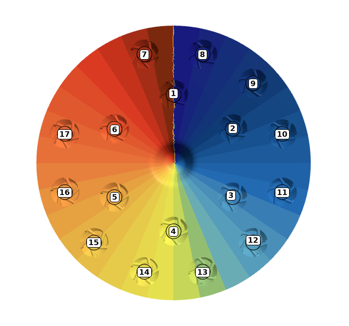
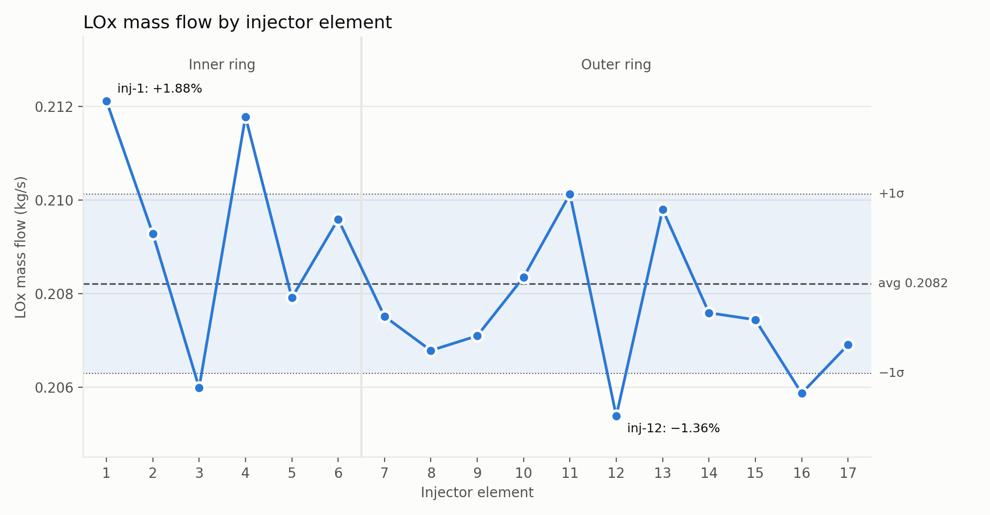
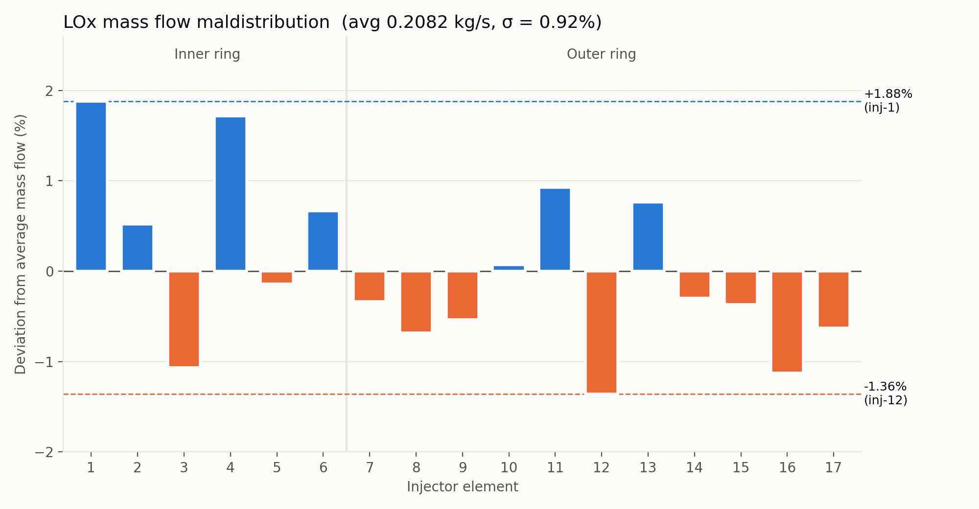
- All 17 elements flow within 2% of the average of 0.2082 kg/s. The largest deviations are +1.88% at inj-1 and −1.36% at inj-12, and the standard deviation across all 17 is 0.92%.
- Why
- The distribution is tight because each element has a 132 psi pressure drop.
- Next
- To reduce the inner-ring bias, I would add a perforated splash plate under the stem to break up the inlet jet.
Stem, plenum and two rings of elements
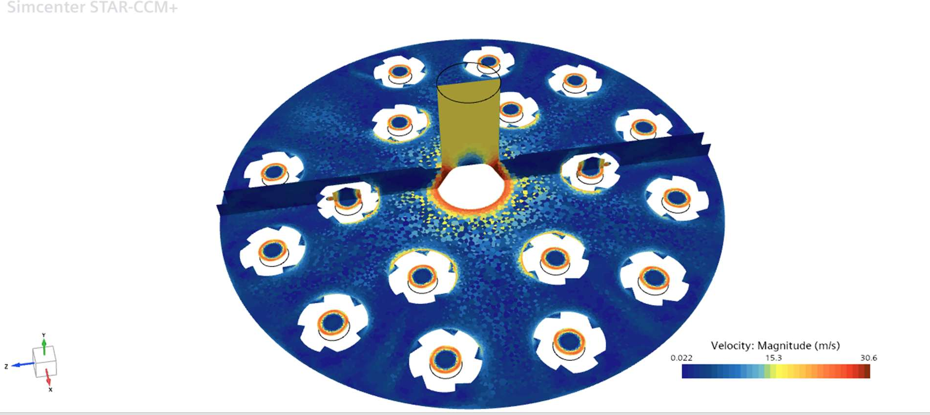
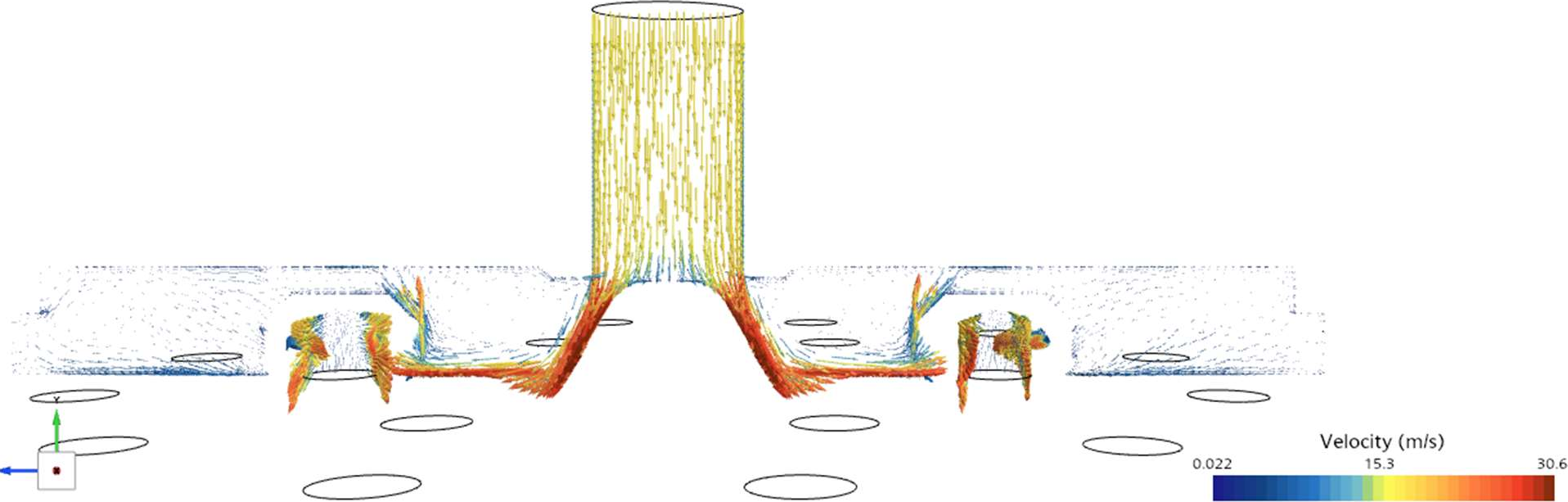
Liquid oxygen enters through a single stem at the top of the manifold. A cone on the plenum floor sits directly under the stem and turns the downward jet outward across the floor.
Assumptions and values
With the total flow fixed at the inlet and the pressure fixed at the outlets, the solver determines how that flow divides among the elements.
| Steady flow | Steady solver |
| Incompressible liquid | ρ = 1141 kg/m³, μ = 1.8e-4 Pa·s |
| Turbulence | RANS, SST k-ω |
| Wall treatment | All y+ |
| Inlet | Mass flow, 3.54 kg/s |
| Outlets (17) | Static pressure, 240 psig each |
| Walls | No-slip, smooth |
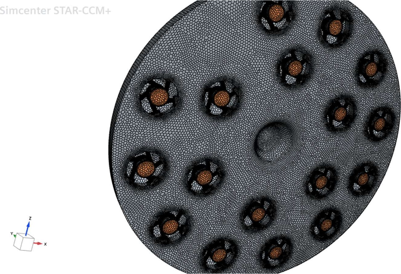
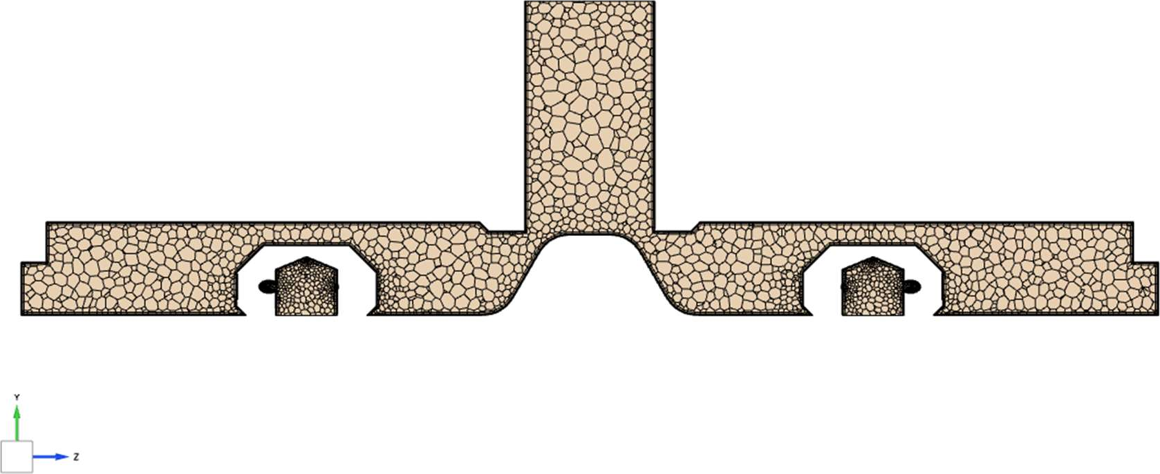
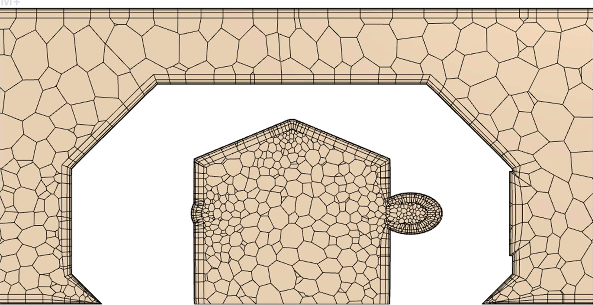
1.72 million polyhedral cells
The elements and their tangential slots have much finer cells than the plenum.
Convergence and sanity checks
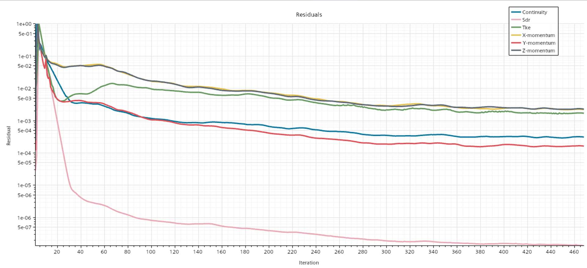
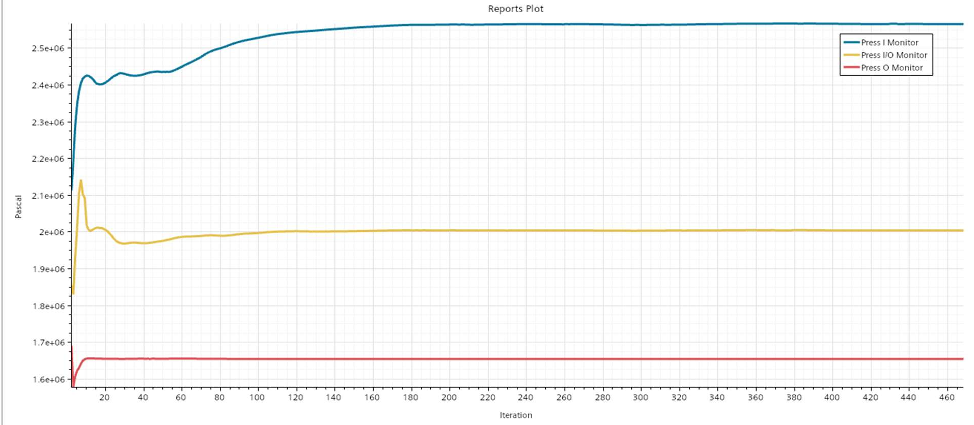
The residuals dropped 3 to 6 orders of magnitude and leveled off by about 300 iterations. To confirm the answer is also physical, I checked four quantities.
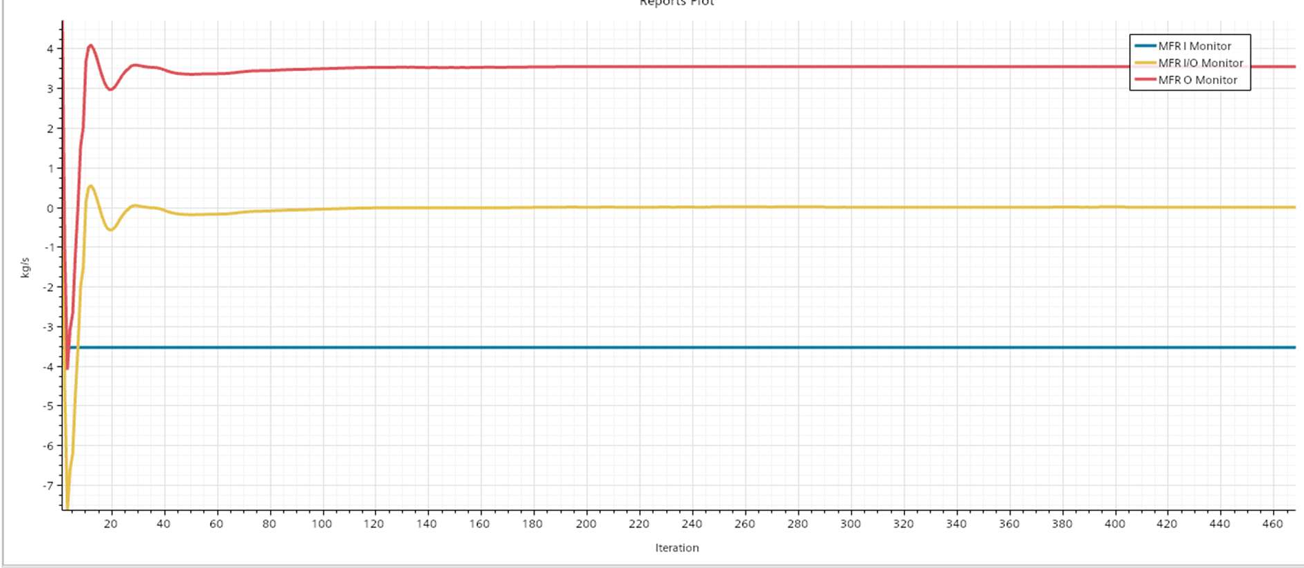
- Continuity error
- 0.013%
- Manifold ΔP
- 132.2 psi
- Outlet pressure
- 239.8 psi
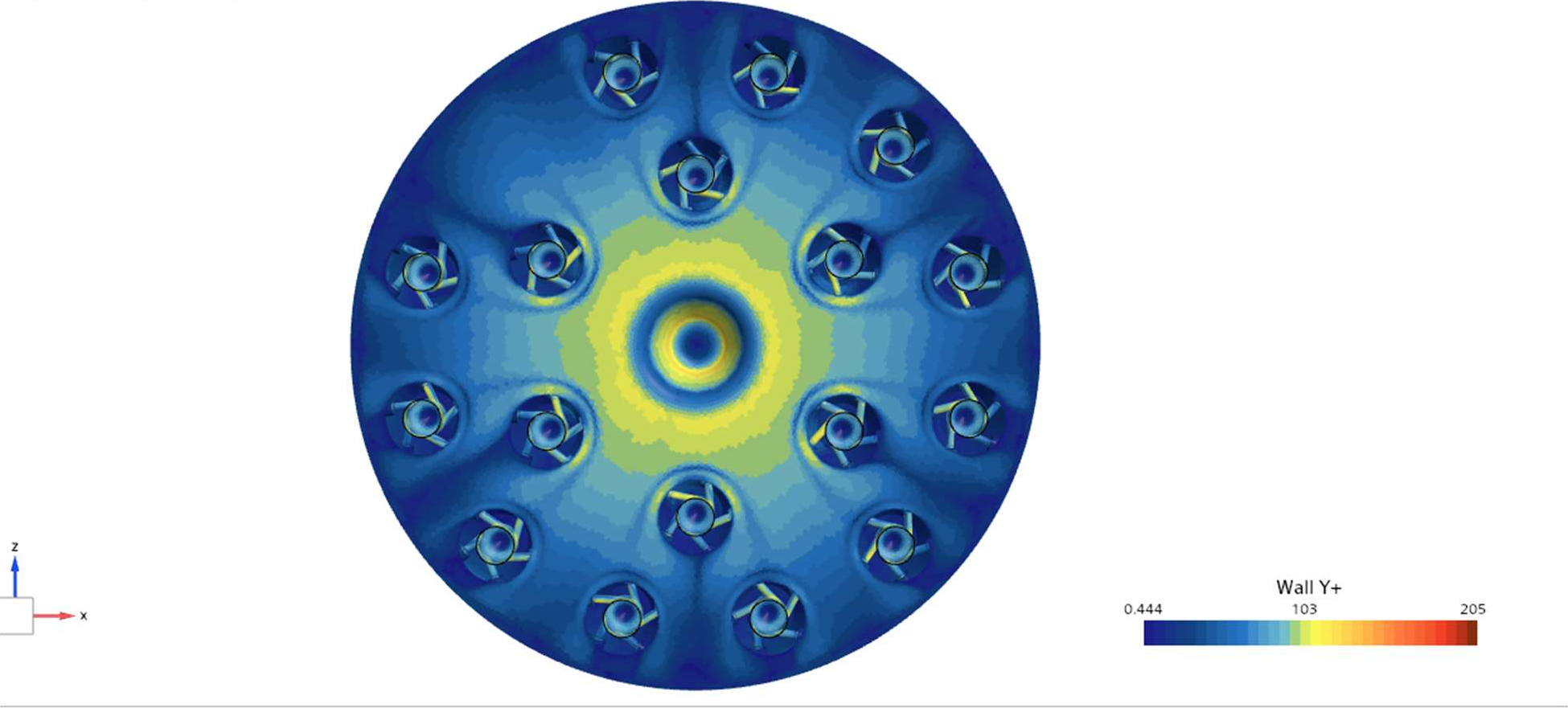
- Wall y+
- 0.4–205
Hand calcs agree with the CFD
Each element acts as an orifice, so its mass flow scales with the square root of its pressure drop.
| Quantity | Hand calc | CFD |
|---|---|---|
| Avg element flow | 3.54 ÷ 17 = 0.2082 kg/s | 0.2082 kg/s (Σ = 3.5396) |
| Stem velocity | ṁ ÷ (ρ·A_stem) ≈ 16.6 m/s * | ≈ 15 m/s in the velocity scene |
| Stem Reynolds no. | ρVD ÷ μ ≈ 1.6 × 10⁶, turbulent | Supports the RANS model |
| Plenum dynamic head | ½ρv² at 3 m/s ≈ 0.7 psi | Tiny next to the 132 psi ΔP |
| Element CdA | ṁ_el ÷ √(2ρΔP) ≈ 4.6 mm² | Uses the CFD ΔP of 132.2 psi |
| Flow sensitivity | δṁ/ṁ ≈ ½ · δP/ΔP (orifice) | +1.88% at inj-1 ⇒ ≈ 5 psi extra |
* Stem diameter ≈ 15.4 mm, inferred from the tutorial's 16.6 m/s inlet velocity and still to be confirmed against CAD.
Every element within ±2% of the average
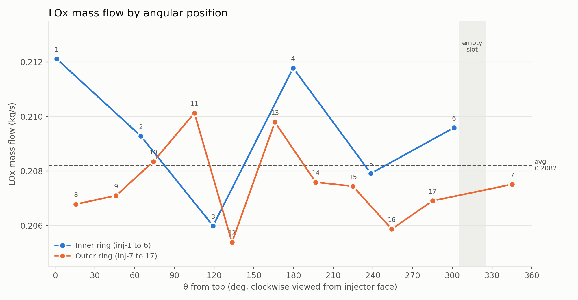
The inner ring averages 0.6% above the mean and the outer ring 0.3% below it. Plotting flow against angle shows no trend around the manifold.
What the flow field shows
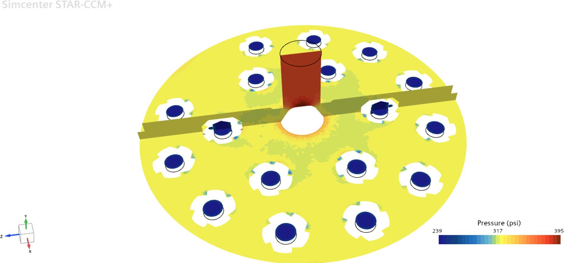
When the LOx leaves the stem, the flow area increases sharply. Continuity requires the velocity to drop to a few m/s, and the pressure in the plenum stays high and close to uniform. Most of the 132 psi pressure drop occurs across the swirl slots.
What would tighten these results
- The modified geometry has not been run yet.
- LOx density and viscosity were held constant, temperature was never an input, and the walls were modeled as smooth.
- Each outlet also has 41 to 48 faces of backflow, caused by the low-pressure swirl core sitting on the outlet plane.
- Some of the ±2% spread may also come from mesh error.