Project 02 · January to May 2026
Mitsubishi 6G72 V6 CAD Assembly
A V6 SOHC engine I reverse engineered in SolidWorks from part drawings and reference dimensions. The crankshaft, camshaft, valve train and a 20+ part accessory drive were all modelled and assembled from scratch, and the whole thing mates together and moves.
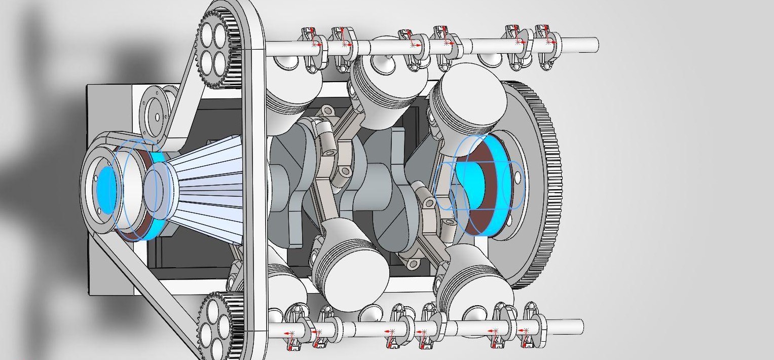
Cutaway view of the pistons, crank, timing belt and both cam banks
- Unique part types
- 40+
- Cylinders, V-configuration
- 6
- Bore
- 91.1mm
- Stroke
- 76mm
Why this project
I wanted practice at two things the robot arm never made me do. The first was working off real part drawings and reference dimensions instead of designing from a blank sketch. The second was managing an assembly big enough that one mistake in one subsystem, a bore diameter or a journal offset, breaks the way a dozen other parts mate.
The 6G72 was the target, a real Mitsubishi V6 SOHC engine that I worked through feature by feature. That meant the cylinder block, the crankshaft and connecting rods, the camshafts and the full valve train with its rocker arms, followers and springs, the timing belt and cam gears, and the intake and exhaust manifolds. Every dimension came off a reference measurement and got constrained with real geometric mates instead of being eyeballed.
I checked the mechanical motion with a SolidWorks Motion Study, so the crankshaft actually drives the pistons and the valve train through the constraints I built rather than sitting in a static exploded view. I did not get to tolerancing given how long the project ran, so what this shows is the assembly complexity and whether the parts move correctly against each other.
How the power flows
The assembly is not a static shell. Every rotating part is constrained to the one before it, so you can step through the chain below and see what drives what.
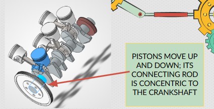
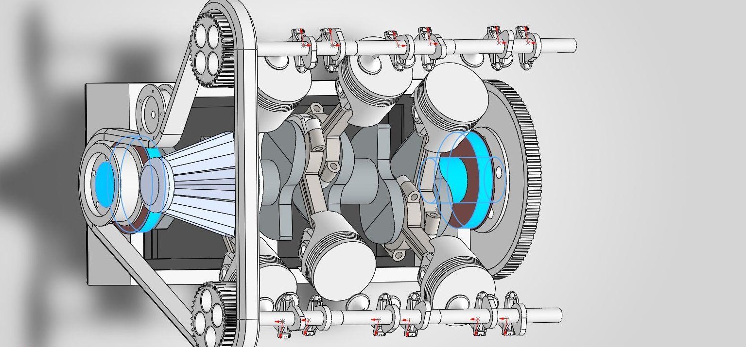
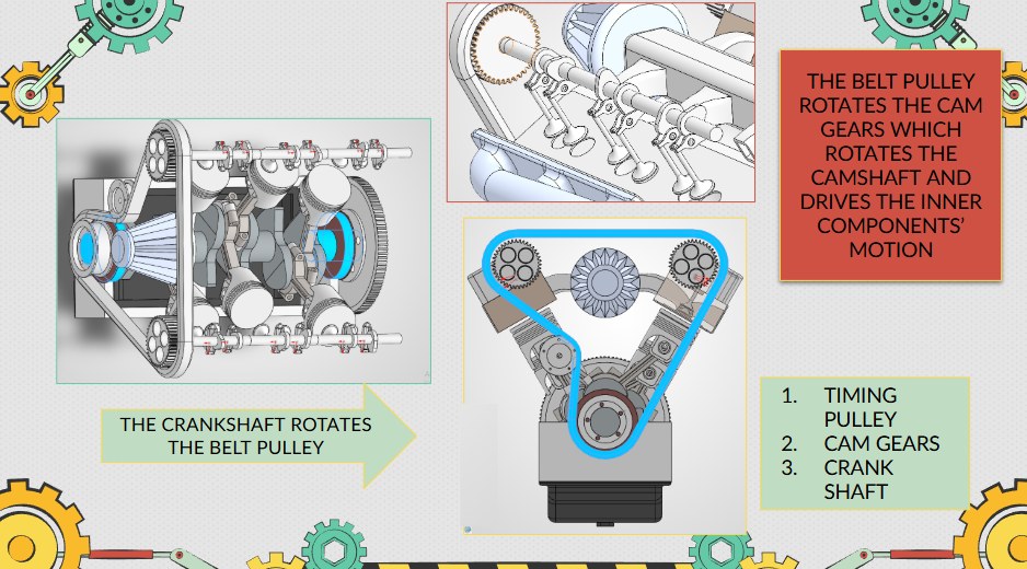
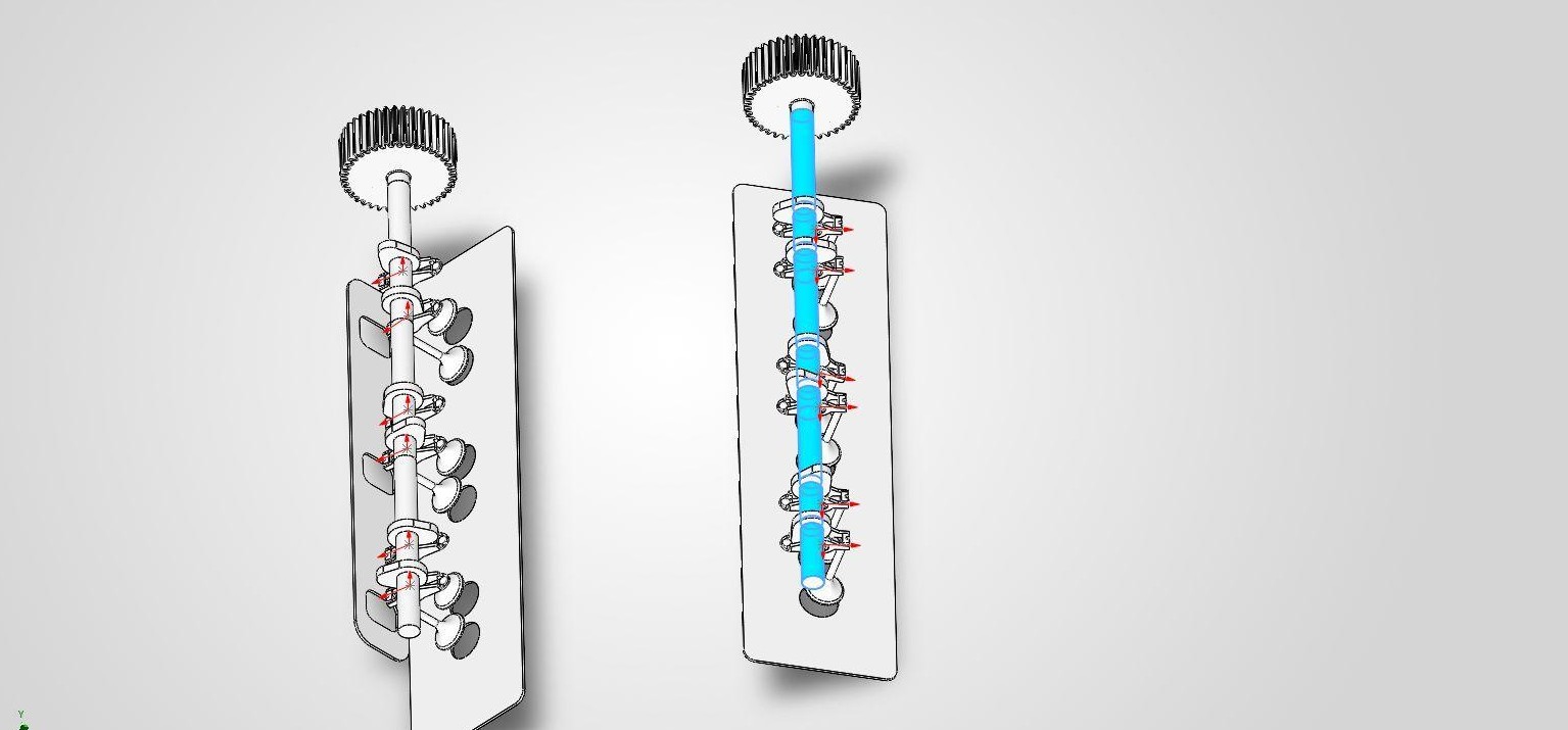
Step 1 of 4
Combustion drives the pistons
Each piston travels up and down in its bore with its connecting rod constrained concentric to the crankshaft journal. Six pistons across two banks put rotational force into the crank.
Model views
The finished assembly from three angles, with the intake and exhaust manifolds, the timing belt and both cylinder banks all in place.
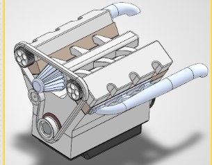
Isometric
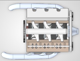
Front elevation
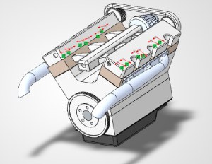
Rear isometric
The assembly
SolidWorks screenshots of the model itself, along with a dimensioned 2D drawing and the full exploded view BOM. The photo of the real 6G72 is there for comparison and is not my own work.
Motion study
Crankshaft rotation drives the pistons, and through the timing belt and cam gears it drives the full valve train. This is an actual kinematic simulation running off the constraints, not a rendered animation.
SolidWorks Motion Study, slowed to 0.75× so it is easier to follow
Key dimensions
| Cylinder bore | 91.1 mm |
| Cylinder stroke | 76 mm |
| Valve spring | 30–34 mm |
| Rod journal | 50 mm |
| Main journal | 60 mm |
| Configuration | V6, SOHC |
Bill of materials
Part of the list, which is enough to show how much has to mate correctly before the assembly will move as one system.
| Part | Qty |
|---|---|
| Engine block | 1 |
| Crankshaft | 1 |
| Crank bushing | 2 |
| Camshaft | 1 |
| Camshaft (opposite side) | 1 |
| Valve | 12 |
| Valve washer | 12 |
| Rocker arm | 12 |
| Rocker follower | 12 |
| Cylinder head | 2 |
| Cylinder head cover | 2 |
| Piston (part 1–4 sets) | 24 |
| Lower block | 1 |
| Oil pan | 1 |
| Intake manifold | 1 |
| Exhaust manifold + mirrored | 2 |
| Exhaust manifold gasket | 2 |
| Head gasket | 2 |
| Cam gear | 2 |
| Flywheel | 1 |
| Timing belt | 1 |
| Pulley | 2 |
| Air filter | 1 |
What I'd build next
What this model shows is synchronized mechanical motion, with multiple axes of rotation all driven from a single input and pulleys and gears holding the timing relationships between them.
The obvious next step is the part I left out on purpose, which is the combustion system. Modelling the fuel path, the injectors and the spark timing would take this from a kinematic assembly to something you could actually simulate as a running engine. That is a harder problem than the geometry was, and it is the one I would want to take on next.